

What is the hardware structure of Hil simulation test required for automatic driving?
HiL(Hardware-in-the-Loop) hardware-in-the-loop simulation test, through the real-time processor to run the simulation model, simulate the actual operating environment, and conduct a comprehensive and in-depth test of the controller. Widely used in automotive electronics such as ECU TCU BCM and other testing. In this way, development time and cost can be significantly reduced.
In general, there are three forms of control system simulation:
1) virtual controller virtual object = dynamic simulation system, is a pure software system simulation;
2) The actual object of the virtual controller is the rapid control prototype (RCP) simulation system, which is a semi-physical simulation of the system;
3) The actual controller virtual object = hardware-in-the-loop (HiL) simulation system is another kind of semi-physical simulation of the system.
The overall architecture of HiL test system is shown in the following figure
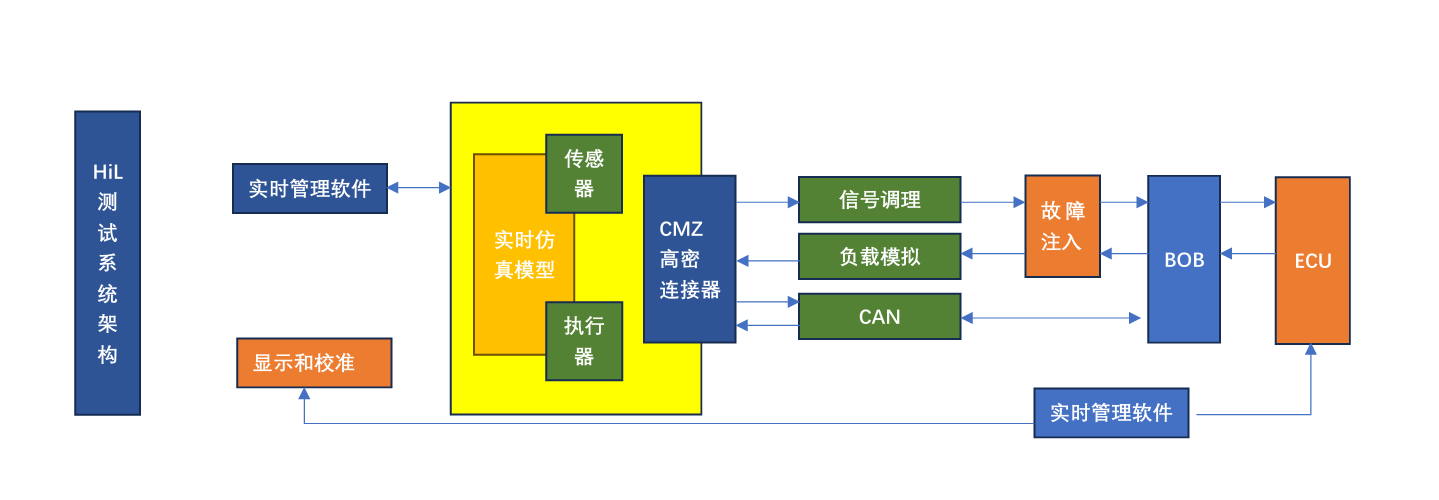
As can be seen from the figure, HiL test system mainly has hardware platform, software platform, simulation model
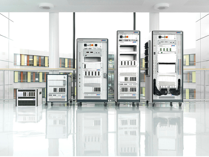
1) Hardware platform: using distributed design mode, the upper computer as the control core of the whole system, mainly responsible for hardware and software configuration and process management, the lower computer to PXI chassis, real-time processor and I/O board as the core, mainly responsible for sequence execution and equipment call. The system hardware platform consists of PXI chassis, real-time processor, I/O board, communication board, power management module, fault injection board, low-voltage programmable power supply, signal conditioning module, cabinet and host computer, coupled with I/O integrated high-density connector and BOB fault diagnosis box.
2) Software platform: The first version includes experimental management software and automated testing software, which realizes the functions of test management, fault injection, test case editing and automated testing.
3) Simulation model: The simulation model provides a complete virtual environment for the HiL system, and the corresponding I/O signal and CAN signal of the tested ECU are matched through the hardware board to realize the seamless connection between the simulation model of the control object and the input and output signals of the controller, thus forming a closed-loop test environment. For example, pure electric vehicle simulation model, including vehicle longitudinal dynamics model, driver model, motor model, power battery model, main reducer model, virtual controller model, I/O model, road and environment model, etc.

The I/O model realizes the signal connection between the vehicle simulation model and the controller under test. The I/O model includes sensor signal output interface, actuator signal acquisition interface, communication interface, etc.
Generally speaking, the whole HIL model has a large number of channels, which requires high quality of simulation signals and needs to be real-time. In the choice of connector, need to use high density, and easy to plug type.
The following CMZ connector is particularly suitable for use in HIL simulation testing as the I/O port of the device.

1. The connector has a high life, up to 10000 times of plug life
2. High signal transmission quality, contact resistance ≤ 15mΩ
3. The insertion and removal process is 0 wear and tear, and the docking can be completed with one click, which is very labor-saving.
4. Environmental adaptability: the working temperature can withstand -55 ℃ ~ 105 ℃, and the neutral salt spray test can reach 96H.
recommend News
Contact Information

Address: Building A38, U Valley, Liandong, Baishazhou, Wangcheng Economic and Technological Development Zone, Changsha City, Hunan Province,China
Public number | tremolo number
Welcome to pay attention to us